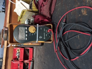
One of Jon’s Digital Volt Ohm Meters (DVOM)
USE THIS INFORMATION AT YOUR OWN RISK!
Mountain States Welder Repair, LLC is not responsible for your repair results. If you are not comfortable performing any of the checks and repairs written here, do not attempt them. Also, if you are not genuinely familiar with the use of a Digital Volt Ohm Meter (DVOM) do not attempt the sections of these tips that require one. Instead, bring your welder into our shop to diagnose and repair for you.
So your Lincoln SA250, Classic 300 or Classic III has quit welding for no apparent reason
These types of welders all have exciter rotors vs exciter armatures. The following quick tips will help you troubleshoot a problem while you are in the field.
Check your leads and lead connections. If you’ve put a whip on your stinger lead, be sure to check that too. Make sure your lead connections are clean and tight. Check over the leads themselves for any damage or kinks.
Check your exciter brushes and slip rings. Shut down the engine and remove the exciter cover. There is one large pan sized cover at the front of the welder. Remove the 4 screws that hold it in place and then pull it off. On the larger bodied SA-250 you must remove the plate below the control panel. If you can’t get to the plate (as in a truck mounted welder) just work from both sides of the machine. There is an upper and lower half to the cover that is over the exciter frame. There will be 4 to 6 screws holding these two covers in place. Remove the screws and remove the upper cover. Be aware when removing the lower cover. Do not allow the cover to touch the battery installed under it. Inspect both exciter brushes. They are the small copper/carbine rectangles with copper wiring connected to them. There is a load spring that keeps the exciter brush pressed to the armature. If the brushes are worn they will allow the load spring to ride on the brush holder instead of the brush. If this is the problem, you will need to replace the brushes. Exciter brushes wear out. It is advisable to keep a spare set.
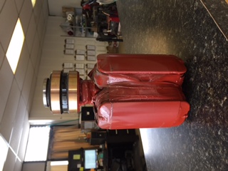
Exciter Rotor
Inspect the exciter rotor slip rings. These are the copper bars that spin and the exciter brushes ride on them. Are they black? Do they look tarnished? Ideally the exciter should be cleaned with a soft Comm Stone. If no stone is available then sand paper will suffice. Use real sand paper and not emery cloth. Emery cloth is coated with a metal oxide and can short your rotor. Clean the slip rings until you see the brass start to shine. Install the brushes, start the engine, and check your weld output.
If you still do not have weld output, shut down the engine again and check the little fuse that is on the inside of your control panel at the lower right side (as you’re facing the panel). You’ll need to use a DVOM (Digital Volt Ohm Meter) to check this. Park the dial of your meter in the ‘Ohms’ position. Check your fuse at both the connectors on either side of the fuse. It should read almost 0 on your meter. Checking at the connectors and not just the fuse rules out any corrosion that can cause the fuse not to make contact with the connectors. If you read very high ohms, then pull your fuse and recheck it. If open, replace it. If it checks out OK, you will need to clean the fuse holder so the fuse can make the connection and let the current flow. If the fuse and connector check out fine, and you still do not have weld output, then STOP.
The next step can be done only if you are fully knowledgeable in the use of the DVOM. If you are not, then bring your machine into the shop to repair.
Next to the fuse that you just checked is a little box, about 1 inch square with 4 connectors on it. This is called a ‘bridge rectifier’ and those connectors are diodes; meaning that they only allow electricity to flow in one direction. On 2 of the 4 connectors are there yellow wires. The yellow wires are for the A/C current that is coming out of the exciter rotor. Leave these intact. The other two wires are the positive and negative for the D/C current. You will be removing these one at a time in order to check the rectifier.
Remove the first of the D/C (non-yellow) wire. With your DVOM, hold the positive lead onto one of the yellow wires where it connects to its spade, and hold the negative lead onto the vacant spade that you just took the D/C wire off of. This should read either very high ohms or very near to 0. Write down the reading. Next, switch the DVOM leads so that you are holding the negative lead onto the same part of the yellow wire, and the positive lead onto the vacant spade. Write down the reading. If you have a high ohm reading the first time, it should read very near to 0 on the second time. If it was near 0 in the first reading than it should read high in the second. Reconnect the D/C wire to the spade.
Disconnect the second D/C (non-yellow) wire and repeat everything that you just did above. (meaning both the other D/C wire and the other yellow wire.) Remember to reconnect the D/C wire when you’re done. You should have gotten the same readings from this side that you got from the other side. If your meter reads 0 or ‘Open’ on all the tests you need to replace the rectifier.